VLAN (SVI)
Switched Virtual Interface
GNS3 가상 에뮬레이터

[지난 시간 복습]
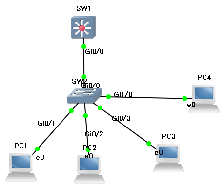
Switch에 4대의 PC를 연결.
Switch Default 상태에서는 모든 포트가 VLAN1로 할당되어 상호 통신이 가능합니다.
각 포트에 VLAN을 할당하여 상호 통신이 차단된 상황을 만들었습니다.
PC5 - VLAN10 - 192.168.10.10/24 GW 192.168.10.1
PC6 - VLAN20 - 192.168.20.20/24 GW 192.168.20.1
PC7 - VLAN30 - 192.168.30.30/24 GW 192.168.30.1
PC8 - VLAN40 - 192.168.40.40/24 GW 192.168.40.1
!
conf t
!
vlan 10,20,30,40
!
vlan 10
name Sales_1Team
!
vlan 20
name Sales_2Team
!
vlan 30
name Sales_3Team
!
vlan 40
name Sales_4Team
!
int g0/1
description ## VLAN10 ##
switchport mode access
switchport access vlan 10
no shut
!
int g0/2
description ## VLAN20 ##
switchport mode access
switchport access vlan 20
no shut
!
int g0/3
description ## VLAN30 ##
switchport mode access
switchport access vlan 30
no shut
!
int g1/0
description ## VLAN40 ##
switchport mode access
switchport access vlan 40
no shut
!
[이번 시간 실습]
SVI를 이용하여 상호 통신이 가능하도록 설정
각 VLAN에 할당된 Host들이 사용할 게이트웨이를 설정
> SVI에 IP 설정
Host 간에 Ping 확인
아래의 설정 값을 넣겠습니다.
!
conf t
ip routing
!
int vlan 10
description ## VLAN10_GW ##
ip add 192.168.10.1 255.255.255.0
no shut
!
int vlan 20
description ## VLAN20_GW ##
ip add 192.168.20.1 255.255.255.0
no shut
!
int vlan 30
description ## VLAN30_GW ##
ip add 192.168.30.1 255.255.255.0
no shut
!
int vlan 40
description ## VLAN40_GW ##
ip add 192.168.40.1 255.255.255.0
no shut
!
routing을 활성화
각 SVI에 IP 설정 및 인터페이스 활성화
[설정 값 확인]
SW3#show vlan br

VLAN Name                             Status    Ports
---- -------------------------------- --------- -------------------------------
1    default                          active    Gi0/0, Gi1/1, Gi1/2, Gi1/3
                                                Gi2/0, Gi2/1, Gi2/2, Gi2/3
                                                Gi3/0, Gi3/1, Gi3/2, Gi3/3
10   Sales_1Team                      active    Gi0/1
20   Sales_2Team                      active    Gi0/2
30   Sales_3Team                      active    Gi0/3
40   Sales_4Team                      active    Gi1/0
1002 fddi-default                     act/unsup
1003 token-ring-default               act/unsup
1004 fddinet-default                  act/unsup
1005 trnet-default                    act/unsup
SW3#show ip
*Jan 15 15:49:47.427: %SYS-5-CONFIG_I: Configured from console by console ro
Codes: L - local, C - connected, S - static, R - RIP, M - mobile, B - BGP
D - EIGRP, EX - EIGRP external, O - OSPF, IA - OSPF inter area
N1 - OSPF NSSA external type 1, N2 - OSPF NSSA external type 2
E1 - OSPF external type 1, E2 - OSPF external type 2
i - IS-IS, su - IS-IS summary, L1 - IS-IS level-1, L2 - IS-IS level-2
ia - IS-IS inter area, * - candidate default, U - per-user static route
o - ODR, P - periodic downloaded static route, H - NHRP, l - LISP
a - application route
+ - replicated route, % - next hop override, p - overrides from PfR
Gateway of last resort is not set
192.168.10.0/24 is variably subnetted, 2 subnets, 2 masks
C 192.168.10.0/24 is directly connected, Vlan10
L 192.168.10.1/32 is directly connected, Vlan10
192.168.20.0/24 is variably subnetted, 2 subnets, 2 masks
C 192.168.20.0/24 is directly connected, Vlan20
L 192.168.20.1/32 is directly connected, Vlan20
192.168.30.0/24 is variably subnetted, 2 subnets, 2 masks
C 192.168.30.0/24 is directly connected, Vlan30
L 192.168.30.1/32 is directly connected, Vlan30
192.168.40.0/24 is variably subnetted, 2 subnets, 2 masks
C 192.168.40.0/24 is directly connected, Vlan40
L 192.168.40.1/32 is directly connected, Vlan40
SW3# !
interface GigabitEthernet0/1
description ## VLAN10 ##
switchport access vlan 10
switchport mode access
negotiation auto
!
interface GigabitEthernet0/2
description ## VLAN20 ##
switchport access vlan 20
switchport mode access
negotiation auto
!
interface GigabitEthernet0/3
description ## VLAN30 ##
switchport access vlan 30
switchport mode access
negotiation auto
!
interface GigabitEthernet1/0
description ## VLAN40 ##
switchport access vlan 40
switchport mode access
negotiation auto
!!
interface Vlan10
description ## VLAN10_GW ##
ip address 192.168.10.1 255.255.255.0
!
interface Vlan20
description ## VLAN20_GW ##
ip address 192.168.20.1 255.255.255.0
!
interface Vlan30
description ## VLAN30_GW ##
ip address 192.168.30.1 255.255.255.0
!
interface Vlan40
description ## VLAN40_GW ##
ip address 192.168.40.1 255.255.255.0
!
PC5 - 192.168.10.10
PC6 - 192.168.20.20
PC7 - 192.168.30.30
PC8 - 192.168.40.40
마지막으로 PC간 Ping 테스트를 해보겠습니다.
PC5> ping 192.168.20.20 -c 10
192.168.20.20 icmp_seq=1 timeout
192.168.20.20 icmp_seq=2 timeout
84 bytes from 192.168.20.20 icmp_seq=3 ttl=63 time=4.956 ms
84 bytes from 192.168.20.20 icmp_seq=4 ttl=63 time=4.680 ms
84 bytes from 192.168.20.20 icmp_seq=5 ttl=63 time=4.327 ms


PC5> ping 192.168.30.30
192.168.30.30 icmp_seq=1 timeout
84 bytes from 192.168.30.30 icmp_seq=2 ttl=63 time=2.497 ms
84 bytes from 192.168.30.30 icmp_seq=3 ttl=63 time=2.486 ms
84 bytes from 192.168.30.30 icmp_seq=4 ttl=63 time=2.654 ms
84 bytes from 192.168.30.30 icmp_seq=5 ttl=63 time=2.917 ms


PC5> ping 192.168.40.40
192.168.40.40 icmp_seq=1 timeout
84 bytes from 192.168.40.40 icmp_seq=2 ttl=63 time=2.957 ms
84 bytes from 192.168.40.40 icmp_seq=3 ttl=63 time=2.927 ms
84 bytes from 192.168.40.40 icmp_seq=4 ttl=63 time=3.018 ms
84 bytes from 192.168.40.40 icmp_seq=5 ttl=63 time=2.746 ms
위의 구성은
L3 스위치1대를 Access Switch 로 이용했을 때의 방식이고
다음 시간엔
L2 스위치를 Access Switch로 놓았을 때
VLAN 간의 통신을 이어서 실습 해보겠습니다.
[다음 시간 구성도]
감사합니다.
'Network' 카테고리의 다른 글
| VTP (VLAN Trunking Protocol) [②] (0) | 2021.01.17 |
|---|---|
| VTP (VLAN Trunking Protocol) [①] (0) | 2021.01.16 |
| VLAN (SVI, Trunk mode) [③] (0) | 2021.01.16 |
| VLAN (Access Mode, Access Vlan) [①] (0) | 2021.01.14 |
| VLAN 이란 (0) | 2021.01.13 |


